 Apres l’utilisation de protocole 433 MHz avec les prises télécommandées (voir mon article Domotique DIY – Partie 3 – Hack des prises télécommandées) nous allons agrandir notre système #DIY avec les interrupteurs / Switch Wifi.
Cahier des charges:
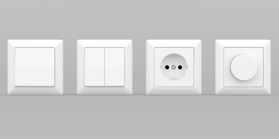
Je voudrais commander facilement via mon système #Domotoque #DIY les différentes prises et interrupteurs de ma maison en utilisant mon réseau Wifi domestique et ma Box Domotique DIY. Il doit être facilement adaptable a tous les interrupteur , prise et lampes.
Matériels
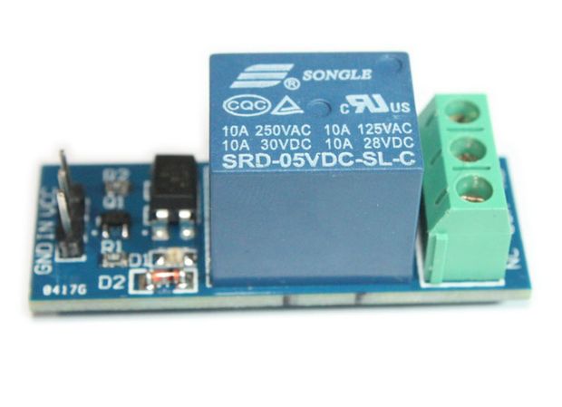
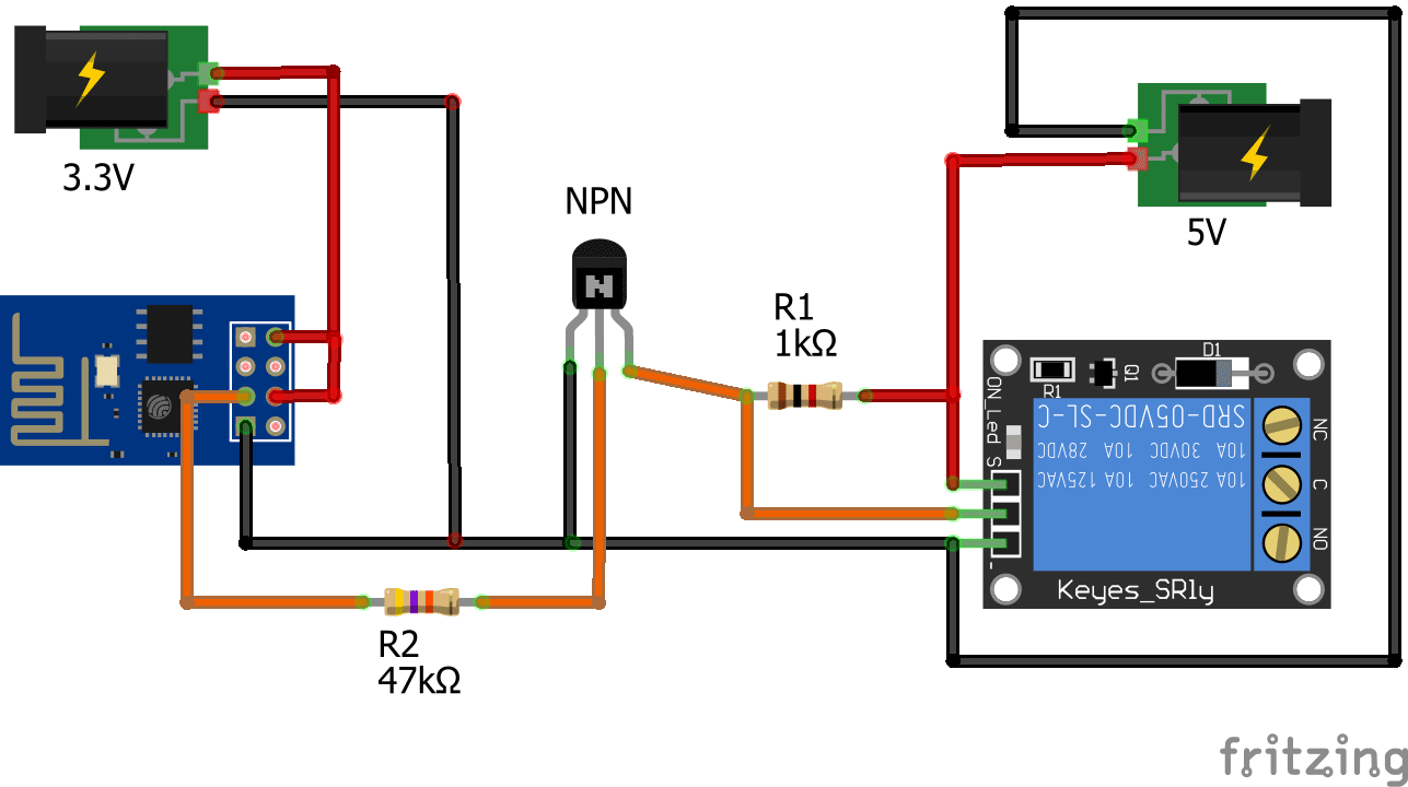
- Relais 5v / 220V
- ESP8266 – 01
- Deux résistances (47k et 1k)
- Transistor NPN
- un peu de courage
Branchement

Programmation ESP8266
Il nous reste de programmer notre ESP et à l’intégrer notre système a nos interrupteurs et prises que nous désirons de domotiser. N’oublier pas de brancher le GPIO 0 à la masse avant d’envoyer votre croquis
1 2 3 4 5 6 7 8 9 10 11 12 13 14 15 16 17 18 19 20 21 22 23 24 25 26 27 28 29 30 31 32 33 34 35 36 37 38 39 40 41 42 43 44 45 46 47 48 49 50 51 52 53 54 55 56 57 58 59 60 61 62 63 64 65 66 67 68 69 70 71 72 73 74 75 76 77 78 79 80 81 82 83 84 85 86 87 88 89 90 91 92 93 94 95 96 97 | /* * This sketch demonstrates how to set up a simple HTTP-like server. * The server will set a GPIO pin depending on the request * http://server_ip/gpio/0 will set the GPIO2 low, * http://server_ip/gpio/1 will set the GPIO2 high * server_ip is the IP address of the ESP8266 module, will be * printed to Serial when the module is connected. */ #include <ESP8266WiFi.h> const char* ssid = "login"; const char* password = "MotDePasse"; // Create an instance of the server // specify the port to listen on as an argument WiFiServer server(80); void setup() { Serial.begin(115200); delay(10); // prepare GPIO2 pinMode(2, OUTPUT); digitalWrite(2, 0); // Connect to WiFi network Serial.println(); Serial.println(); Serial.print("Connecting to "); Serial.println(ssid); WiFi.begin(ssid, password); while (WiFi.status() != WL_CONNECTED) { delay(500); Serial.print("."); } Serial.println(""); Serial.println("WiFi connected"); // Start the server server.begin(); Serial.println("Server started"); // Print the IP address Serial.println(WiFi.localIP()); } void loop() { // Check if a client has connected WiFiClient client = server.available(); if (!client) { return; } // Wait until the client sends some data Serial.println("new client"); while(!client.available()){ delay(1); } // Read the first line of the request String req = client.readStringUntil('\r'); Serial.println(req); client.flush(); // Match the request int val; if (req.indexOf("/gpio/0") != -1) val = 0; else if (req.indexOf("/gpio/1") != -1) val = 1; else { Serial.println("invalid request"); client.stop(); return; } // Set GPIO2 according to the request digitalWrite(2, val); client.flush(); // Prepare the response String s = "HTTP/1.1 200 OK\r\nContent-Type: text/html\r\n\r\n<!DOCTYPE HTML>\r\n<html>\r\nGPIO is now "; s += (val)?"high":"low"; s += "</html>\n"; // Send the response to the client client.print(s); delay(1); Serial.println("Client disonnected"); // The client will actually be disconnected // when the function returns and 'client' object is detroyed } |
/*
 *  This sketch demonstrates how to set up a simple HTTP-like server.
 *  The server will set a GPIO pin depending on the request
 *    http://server_ip/gpio/0 will set the GPIO2 low,
 *    http://server_ip/gpio/1 will set the GPIO2 high
 *  server_ip is the IP address of the ESP8266 module, will be
 *  printed to Serial when the module is connected.
 */

#include <ESP8266WiFi.h>

const char* ssid = "login";
const char* password = "MotDePasse";

// Create an instance of the server
// specify the port to listen on as an argument
WiFiServer server(80);

void setup() {
  Serial.begin(115200);
  delay(10);

  // prepare GPIO2
  pinMode(2, OUTPUT);
  digitalWrite(2, 0);

  // Connect to WiFi network
  Serial.println();
  Serial.println();
  Serial.print("Connecting to ");
  Serial.println(ssid);

  WiFi.begin(ssid, password);

  while (WiFi.status() != WL_CONNECTED) {
    delay(500);
    Serial.print(".");
  }
  Serial.println("");
  Serial.println("WiFi connected");

  // Start the server
  server.begin();
  Serial.println("Server started");

  // Print the IP address
  Serial.println(WiFi.localIP());
}

void loop() {
  // Check if a client has connected
  WiFiClient client = server.available();
  if (!client) {
    return;
  }

  // Wait until the client sends some data
  Serial.println("new client");
  while(!client.available()){
    delay(1);
  }

  // Read the first line of the request
  String req = client.readStringUntil('\r');
  Serial.println(req);
  client.flush();

  // Match the request
  int val;
  if (req.indexOf("/gpio/0") != -1)
    val = 0;
  else if (req.indexOf("/gpio/1") != -1)
    val = 1;
  else {
    Serial.println("invalid request");
    client.stop();
    return;
  }

  // Set GPIO2 according to the request
  digitalWrite(2, val);

  client.flush();

  // Prepare the response
  String s = "HTTP/1.1 200 OK\r\nContent-Type: text/html\r\n\r\n<!DOCTYPE HTML>\r\n<html>\r\nGPIO is now ";
  s += (val)?"high":"low";
  s += "</html>\n";

  // Send the response to the client
  client.print(s);
  delay(1);
  Serial.println("Client disonnected");

  // The client will actually be disconnected
  // when the function returns and 'client' object is detroyed
}Utilisation
Notre système et opérationnel pour commander notre interrupteur ou prise il suffit d’envoyer la commande http://server_ip/gpio/0 pour éteindre et http://server_ip/gpio/1 pour allumer.
Intégration
HC2 Fibaro
- créer un nouveau module virtuel
- insérer deux boutons ON et OFF
- coller le code LUA suivant
1 2 3 4 5 6 7 8 | --[[ %% properties %% globals --]] -- Bouton OFF local http = net.HTTPClient(); http:request("http://IP_ESP8266/gpio/0"); |
--[[
%% properties
%% globals
--]]

-- Bouton OFF
local http = net.HTTPClient();
http:request("http://IP_ESP8266/gpio/0");1 2 3 4 5 6 7 8 | --[[ %% properties %% globals --]] -- Bouton ON local http = net.HTTPClient(); http:request("http://IP_ESP8266/gpio/1"); |
--[[
%% properties
%% globals
--]]

-- Bouton ON
local http = net.HTTPClient();
http:request("http://IP_ESP8266/gpio/1");Jeedom
- Plugin > Programmation > Script
- Ajouter > Nom de l’équipement > D’accord
- Commandes > Nom > On
- Commandes > Type script > HTTP
- Commandes > Type > Action
- Commandes > Requête > IP_ESP8266/gpio/1
- Commandes > Nom > Off
- Commandes > Type script > HTTP
- Commandes > Type > Action
- Commandes > Requête > IP_ESP8266/gpio/0
Si vous avez des questions n’hésitez pas de les poser ici 🙂


[…] Domotique DIY – Partie 7 – Interrupteur intelligent Wifi : Domotique-Home […]
Bonjour, bon article, mais je me pose une question : Comment rentrer tout ça dans ma boite d’encastrement ? Une photo ne serait pas de trop. Merci et bonne continuation
Bonjour
Très interessant mais à partir de “Intégration”, on ne comprend plus ce qu’on doit faire ?
Vous proposez apparement un code LUA mais on ne peux injecter un code LUA dans l’esp à partir du moment où on a travaillé avec l’IDE arduino il me semble !
Bonjour @harold,
La partie intégration comporte 2 sous parties.
un exemple d’intégration dans la box domotique Home Center 2 (HC2) de Fibaro qui se programme en LUA, d’ou le code réservé pour cette Box et non pour l’ ESP.
et un deuxième exemple d’intégration dans la Box domotique Jeedom
Vous pouvez également commander l’interrupteur avec un simple navigateur internet (IE, Chrom, FF, Opera…) avec une simple requête HTTP:
il suffit d’envoyer
http://server_ip/gpio/0 pour etindre
et
http://server_ip/gpio/1 pour allumer.
les possibilité sont grande.
Hésitez pas de publier votre cas ici.
Bonjour,
Pardonnez ma question triviale, mais quelle est la marque des prises que vous avez utilisées en illustration de votre article? Je les trouve particulièrement élégantes.
Merci!
Pour domotiser une prise électrique il y a aussi des relais 433Mhz qui sont pas mal.
Le mode opératoire avec un exemple de domotisation de multiprise est décrit dans cet article : https://framboiseaupotager.blogspot.fr/2018/02/dans-un-de-mes-precedents-articles-ici.html
Bonjour,
Débutant dans électronique, je voudrais faire le même montage avec ESP8266 – 01 mais avec un relais double et en 12v, les résistances sont-elles de la même capacité que celui en 5v ?
Si toute fois cela pouvait être accompagné d’un schéma se serait le pied
Merci de votre aide
Bonjour,
Tout dépend de l’intensité.
Il faut que tu appliques la loi d’ohm
R=U/I pour calculer tes résistances.
Bonsoir,
Merci de votre réponse mais je dois me rendre à l’évidence, je n’y arrive pas
lien du relais que je voudrai connecter à l’esp-01 :
https://fr.aliexpress.com/item/4000184549840.html?spm=a2g0s.9042311.0.0.5c806c3734mXRw
Se serait sympa de me faire un petit schéma de montage.
En vous remerciant
Bonsoir,
Suis toujours avec mon problème insoluble pour moi.
IL y aurait pas une p’tite âme charitable pour me venir en aide
Merci bcp
Bonsoir Pierre Frank.
Vous voulez faire quoi exactement
Je vais essayer de vs aider.
Bonjour,
Merci de votre réponse R.Syrek.
Je voudrais faire exactement le même montage mais avec un double relais 12v, (celui indiqué dans le lien de mon message précédent) j’ai essayer comme indiqué sur le schéma mais cela ne fonctionne pas mon esp01 configuré avec Tasmota ne veut pas actionner les relais
Cordialement
Bonjour,
Je viens de regarder votre relais, il peux être alimenté en 5V sans problèmes.
Vous avez juste a faire le même chemin pour les deux sorties et brancher:
ESP GPIO 2 sur IN1
ESP GPIO 0 sur IN2
(2x NPN + 2x R1 et 2x R2)
et bien configurer Tasmota.
Bonsoir R.Syrek
Merci de votre réponse, mais si je pouvais l’alimenter en 12v ce serait super, ce qui m’éviterai d’avoir un 2ème convertisseur (1 pour le 3.3v de l’esp et un pour le relais converti en 5v) le courant qui arrive est du 12v le tout servira à faire tourner dans les 2 sens un moteur lui aussi est en 12v .
Cordialement
Bonjour,
Je viens d’essayer le relais n’accroche pas s’il est monté en 5v, par contre en 12v il accroche bien, mais des qu’on le bascule en off la led du relais reste un tout petit peu allumée tout en scintillant. Est-ce un problème de résistance.
Merci de votre réponse
Cordialement